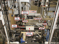
| • | Case Robot X, Case Robot Z, Robot Vacuum, Load Vacuum, Case Pusher: |
| o | Case Robot X & Case Robot Z: The robot is made of the servo-driven Case Robot X (SM11) axis and the servo-driven Case Robot Z (SM10) axis. The Case Robot X will move the robot tooling in the horizontal plane, while the Case Robot Z will move the robot tooling in the vertical plane. The robot tooling consists of a set of vacuum cups which will be used to hold onto a case blank while the blank is being set up |
| o | At the beginning of the robot cycle, the tooling will move toward the leading blank in the magazine. When the vacuum cups are against the leading blank, the Setup Vacuum (SV45402) is turned on |
| o | The robot moves the tooling away from the magazine to the setup station, bringing a case blank with it. During this motion, the case blank opens up |
| o | When the tooling reaches the end of the setup motion, the Load Vacuum (SV35205) is turned on and the air cylinder-controlled cups are moved up to the case bottom horizontal flaps. At this time, the load vacuum cups grab hold of the bottom horizontal flap. |
| ▪ | When the case is filled, the Load Vacuum Retract (SV35506) releases the flaps and lowers the air cylinder controlled cups |
| o | As the load vacuum cups grab the case blank, the funnels move toward the case to hold the case open |
| o | After the case blank has been setup, the robot tooling will release the blank by turning off the Setup Vacuum. The robot tooling can then be moved away from the case at setup. The tooling will be moved up and over the setup case while it returns to the start position in front of the magazine. The Case At Load (PE46601) photo eye is used to determine if the setup case is correctly setup. If the Case At Load photo eye detects the top horizontal case flap and the Load Vacuum is made, the case is setup properly. If the case is not properly setup, a fault status is set and an improper case setup message is displayed |
| o | While the Case Robot X is setting up the case, the Case Pusher (SV45401) attached to Case Robot X will push the previous case from the load position into compression |
| o | The Case Robot X, Case Robot Z, Robot Vacuum, Load Vacuum and Case Pusher are slaves to the Master. The motion profile for the Case Robot X and Case Robot Z, and the timing for the Robot Vacuum, Load Vacuum, and Case Pusher are provided through electronic cam tables |
| • | Funnel In Out, Funtucker In Out: |
| o | The funnels are made of the servo-driven Funnel (SM13) and the servo-driven Funtucker (SM14). The Funnels are used to hold the case open and to provide a guide for the stack as the loader fills the case blank. As the case blank is being brought to the setup station, the air cylinder-driven Funnel In Out (SV35203) and the air cylinder-driven Funtucker In Out (SV46506) move the funnel assemblies toward the case. When the case is positioned in the setup station by the robot, the funnels rotate toward the case. When the funnels are fully rotated toward the case, the funnel tips will be inside the case past the score line. This positioning will provide a good transfer of product into the case blank. As the case is being filled, the Funnel In Out and the Funtucker In Out move the funnel assemblies away from the case. This action brings the funnel tips outside of the score line of the case, clear of the product in the case. After the case is filled, the funnels rotate away from the case |
| o | The Funnel and Funtucker are slaves to the Case Former Master. The motion profile for the Funnel and Funtucker are provided through electronic cam tables |
| o | The purpose of the Case Tuckers is to fold the case flaps. The tuckers are made of the servo-driven Tucker (SM15) and the servo-driven Funtucker (SM14), and are used to fold the trailing vertical flaps. Before the beginning of the tuck motion for the Funtucker, the air cylinder-driven Funtucker In Out moves the Funtucker assembly toward the case |
| o | The Tucker and Funtucker are slaves to the Master. The motion profile for the Tucker and Funtucker are provided through electronic cam tables |
| o | The Loader Backstop (SM09) is driven by servo motor. The Loader Backstop is used to keep product from sliding through the case as the cartons are being pushed into the case from the opposite side via the loader |

| o | The glue station is made of four solenoid-controlled glue guns: Fixed Top Glue (SV30400), Adjustable Top Glue (SV30402), Fixed Bottom Glue (SV30401) and Adjustable Bottom Glue (SV30403). While the case is being moved from the setup/load station to the compression station, glue stitches will be applied to vertical flaps. The Distorted Case (PE46604) photo eye will be used to determine when a case is present for glue to be applied. The timing of the glue stitches will be based on the position of the Case Flights (SM12) through an electronic cam table. The setting of the stitches will be set by the operator from the glue page in the HMI. If the application of the glue stitch is interrupted for any reason, the remainder of the stitch pattern for that case will not be applied. |
| o | Interrupted glue application might be caused by the following conditions: |
| ▪ | no case is detected to apply the glue |
| ▪ | a glue gun was dispensing glue longer than the predetermined period of time |
| ▪ | the machine is cycling at a rate less than the predetermined low speed rate for glue |
| ▪ | the machine was stopped in the middle of the stitch pattern |
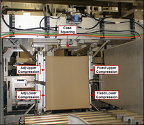
| o | As the product is being transferred past glue into compression, a Case Squaring (SV45403) cylinder is extended in compression. This acts as a stop, but also ensures the case will be square prior to the compression plates folding the flaps |
| o | Compression is made up of the servo-driven Fixed Lower Compression (SM19), the Adjustable Lower Compression (SM20), the Fixed Upper Compression (SM21) and Adjustable Upper Compression (SM22). Compression is used to compress glue with compression plates while the glue sets. After a case is placed into the compression station, the Fixed Lower Compression, Adjustable Lower Compression, Fixed Upper Compression and Adjustable Upper Compression move compression plates to the compression position. Before the case in compression can be removed, the compression plates are moved to the release position |
See also: Drive Function & Associated Devices


